")
Syntezer DDS V3.1 en
- Details
- Category: DDS Synthesizers
- Published: Thursday, 04 April 2013 13:09
- Hits: 10366

Building a synthesizer for some people and for my TRX Taurus I realized that I would have some additional features and some improvements. I created the next version of DDS using processor Atmega8. The system is versatile because you can choose the bandwidth that we have on the radio, you can enter an intermediate, and we can add or subtract intermediate frequecy. This eliminates the need to create multiple versions of the program, because this one fits into all possible combinations of bandwidth and crystal filter. The synthesizer has a memory setting. The system has also step display, and adjust the display brightness. DDS-board is small so it is easy to push it somewhere into the finished radio.
Basic parameters::
Operating range 0-40Mhz
Signal level 1 Vpp @ 200ohm
Step 10kHz, 1khz, 100hz, 10hz
16x1 LCD display
Power suply 5V 0.5A
P1 - band 160m, 80m, 40m, 30m, 20m, 17m, 15m, 12m, 10m, generator
P2 - Intermediate 0 - 20Mhz
P3 - add or subtract intermediate frequecy
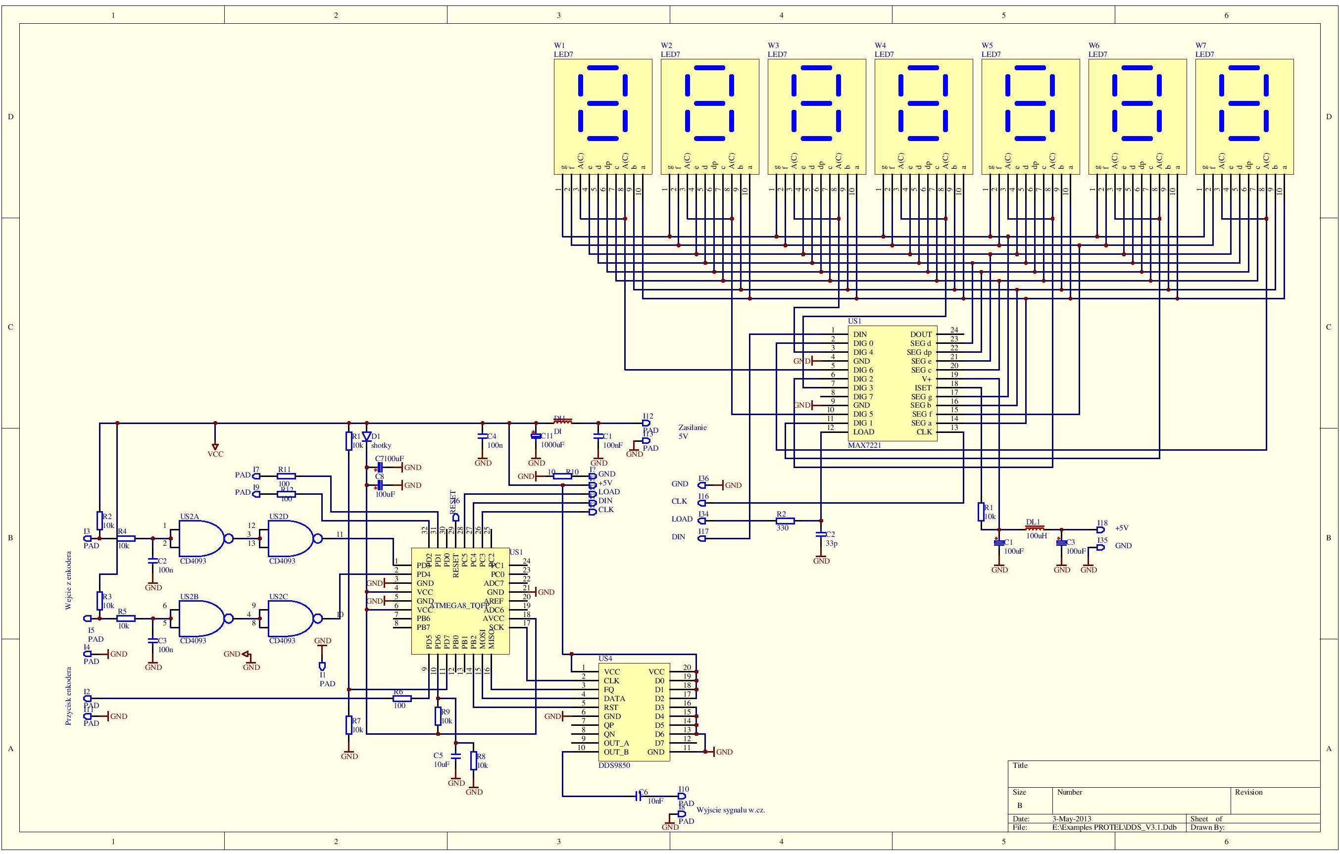
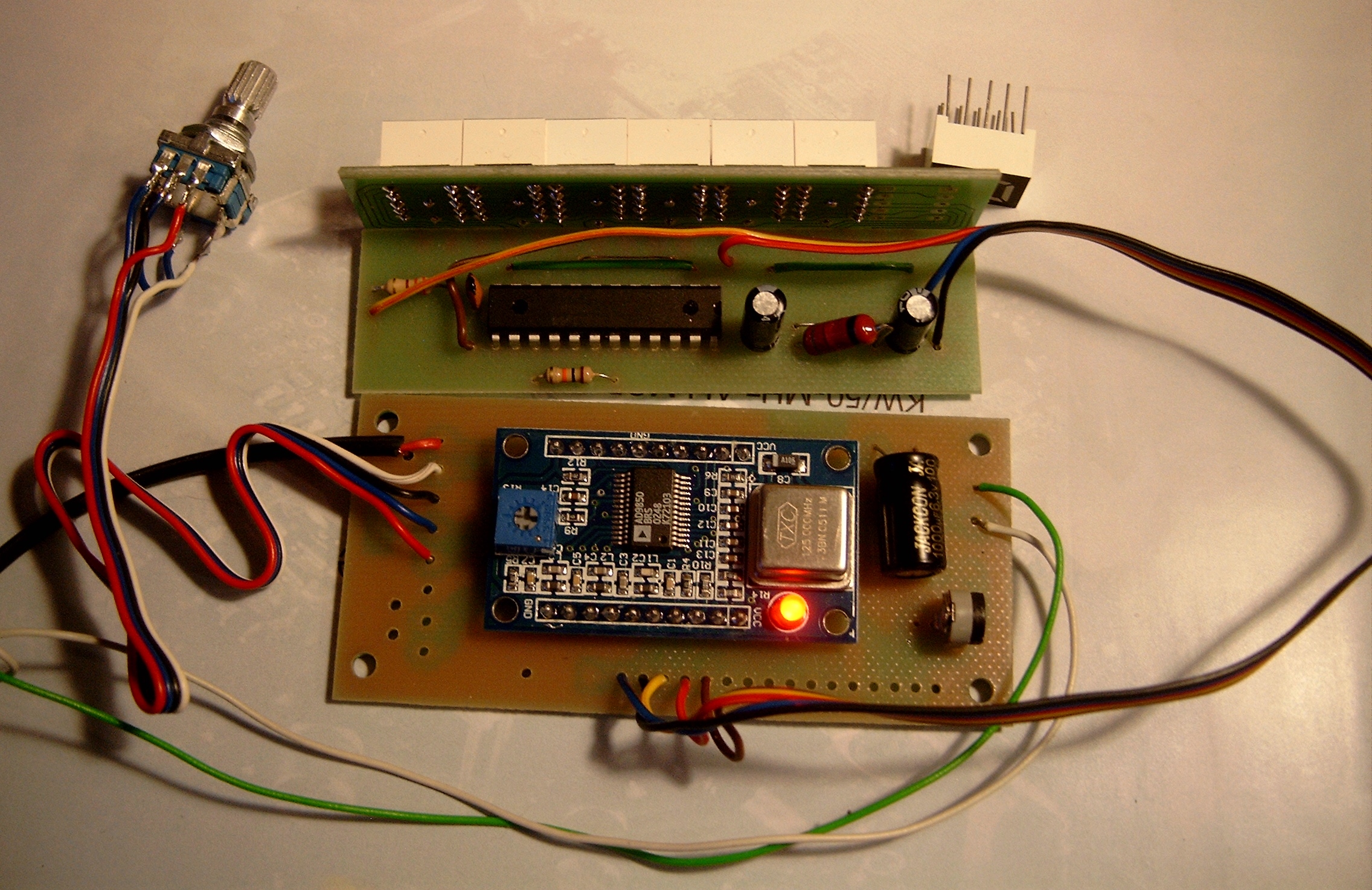
The synthesizer consists of two modules, LED display board and the board DDS / processor.
Both models are powered by 5V.
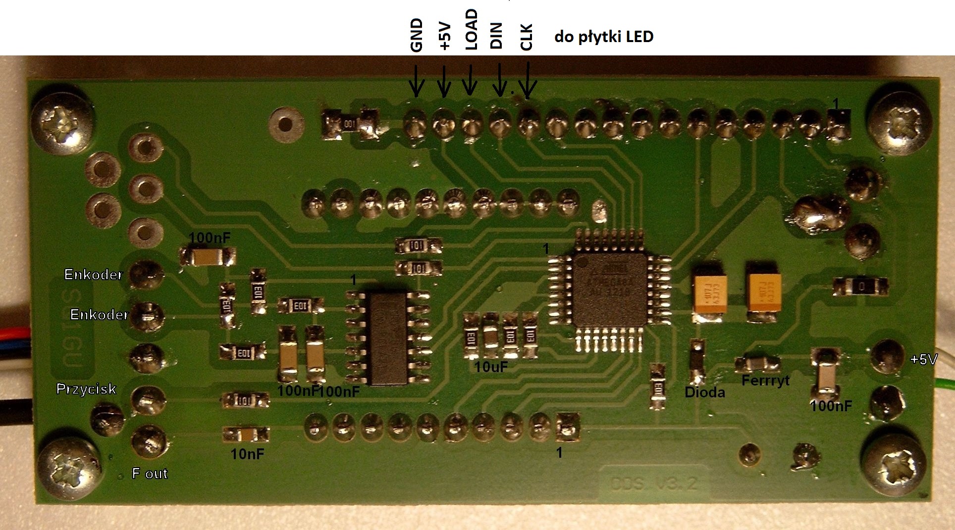
The processor controls the display with 3-line control: DIN, CLK, LOAD
The CPU board is connected to the rotary encoder with push button, which performs all setting and adjustment.
By turning the knob You can change the frequency, by pressing the encoder You can change step (10hz, 100hz, 1khz, 10khz).
Pressing the encoder at least two seconds enter the brightness adjustment (16 levels of brightness).
When you power off the synthesizer, actual frequecy is written to the memory.
Setting the bandwidth and intermediate frequency:
Press the encoder and turn the power on. Displays P1 and the currently set bandwidth. Rotate the knob to select the desired band or a generator. Then press and hold the encoder until the P2, let go, and shows the actual frequency of the intermediate. Set the desired frequency (pressing the button changes the tuning step). In the generator mode You should set an intermediate to 0.
Next, press and hold the encoder until the P3 appear to select -f or +f, for adding or subtracting intermediate frequency. Again press the encoder and the system goes to normal operation with the new settings.
Change Band: (multi-band operation):
Although the synthesizer is dedicated to one-band transceiver, You can change band using button UP and DOWN connected to J7 and J9. After a power cycle synthesizer is set to the band selected in the menu.
Reset and initialize:
Connect J7 to gnd and turn the power on. After E letter on the screen disconnect J7.
Parts list:
AD9850 module
US1 – ATMEGA8a
US2 – CD4093
R10,R11,R12 – 100ohm
R1,R2,R3,R4,R5,R6,R7,R8,R9 – 10k
C1,C2,C3,C4 - 100nF
C5 - 10uF
C6 -10nF
C7,C8 - 100uF
C11- 1000uF
F – ferryte core
D1 - dioda shotky
encoder EC11
U3 – MAX7219
W1,W2,W3,W4,W5,W6,W7 - AS-03911AMG
R8 – 10K
R9 – 330ohm
C7,C8 – 100uF
C9 – 33pF