")
Syntezer DDS V3.2 en
- Details
- Category: DDS Synthesizers
- Published: Sunday, 21 April 2013 20:21
- Hits: 9765
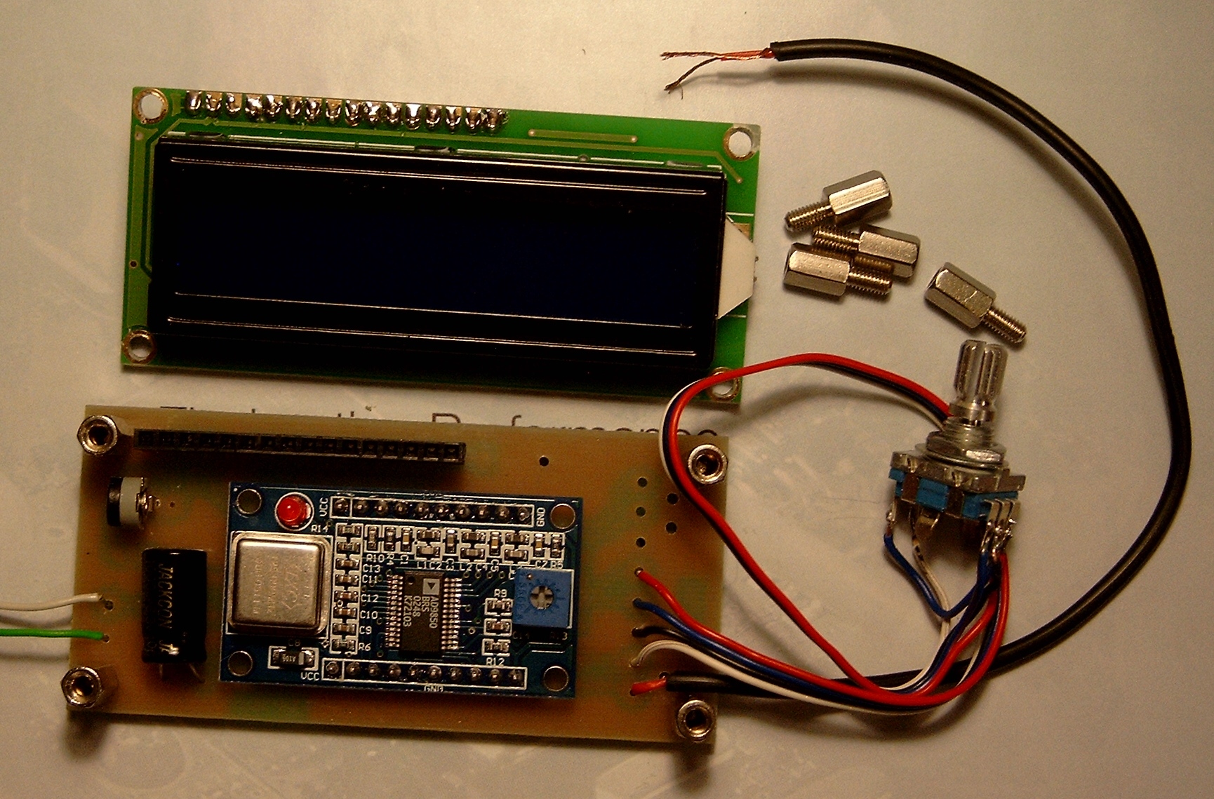
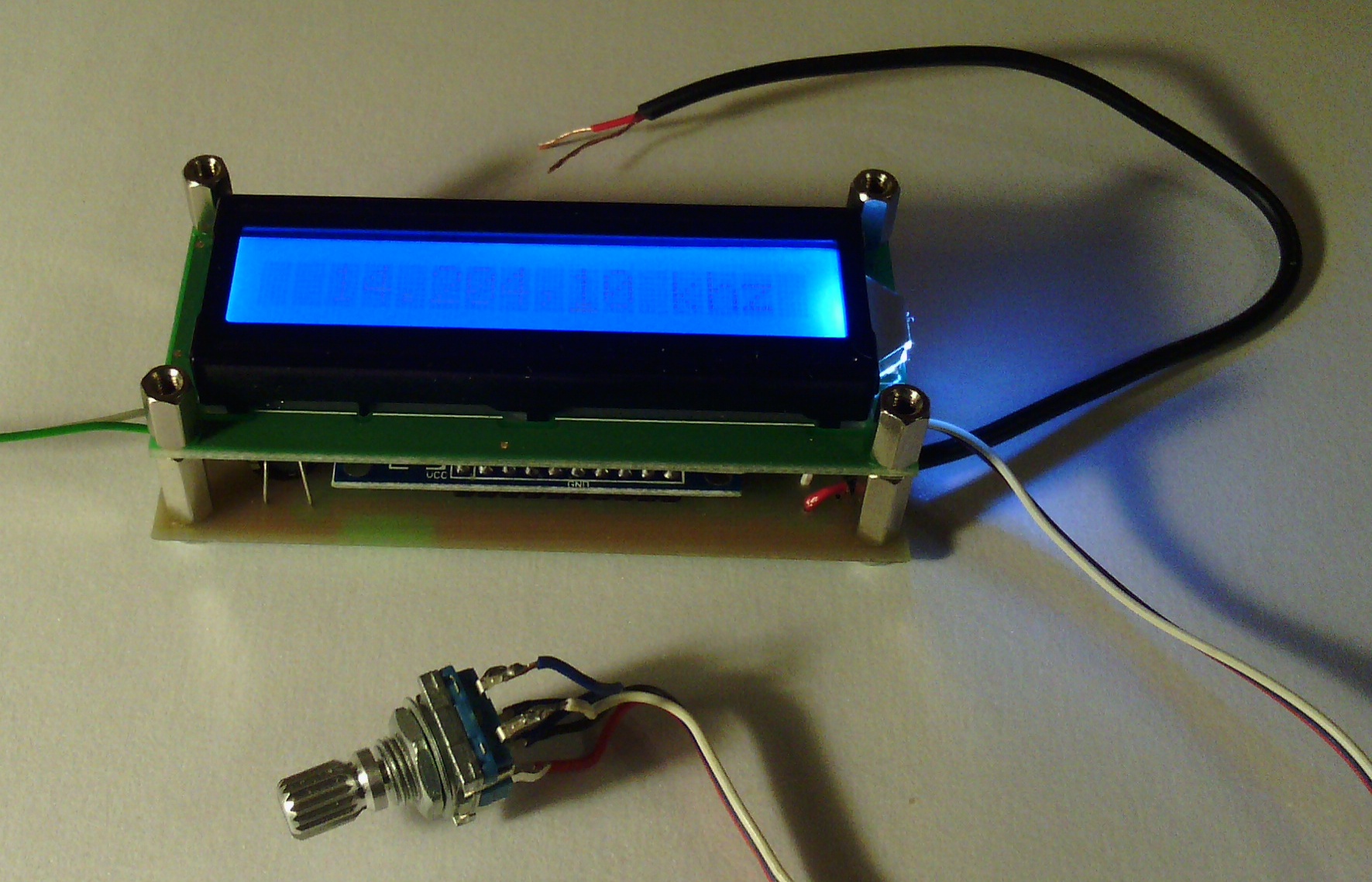
Simple and cheap DDS synthesizer with LCD display. A lot of people have asked about such solution and finally I have designed It. Synthesizer board is the same size of the display, so you can easily mount them together and place in any TRX.
Basic parameters:
Operating range 0-40Mhz
Signal level 1 Vpp @ 200ohm
Step 10kHz, 1khz, 100hz, 10hz
16x1 LCD display
Power suply 5V 0.5A
firmware V3.2a
P1 - band 160m, 80m, 40m, 30m, 20m, 17m, 15m, 12m, 10m, generator
P2 - Intermediate 0 - 20Mhz
P3 - add or subtract intermediate frequecy
The CPU board is connected to the rotary encoder with push button, which performs all setting and adjustment.
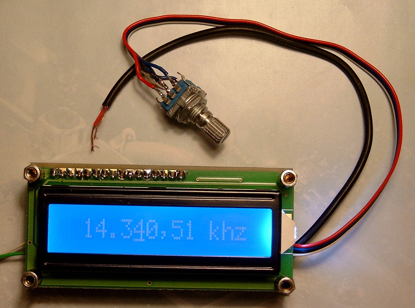
By turning the knob You can change the frequency, by pressing the encoder You can change step (10hz, 100hz, 1khz, 10khz).
When you power off the synthesizer actual frequecy is written to the memory.
Setting the bandwidth and intermediate frequency:
Press the encoder and turn the power on. Displays P1 and the currently set bandwidth. Rotate the knob to select the desired band or a generator. Then press and hold the encoder until the P2, let go, and shows the actual frequency of the intermediate. Set the desired frequency (pressing the button changes the tuning step). In the generator mode You should set an intermediate to 0.
Next, press and hold the encoder until the P3 appear to select -f or +f, for adding or subtracting intermediate frequency. Again press the encoder and the system goes to normal operation with the new settings.
Change Band: (multi-band operation):
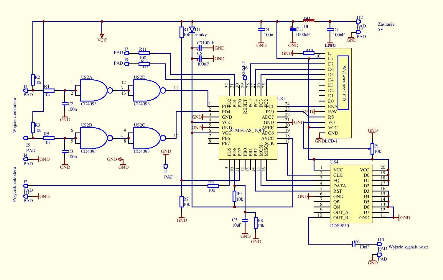
Although the synthesizer is dedicated to one-band transceiver, You can change band using button UP and DOWN connected to J7 and J9. After a power cycle synthesizer is set to the band selected in the menu.
Reset and initialize:
Connect pin J7 to gnd and turn the power on. After " inic." on the screen disconect J7.
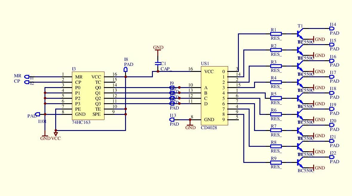
Band decoder:
There is a band dekoder supported.
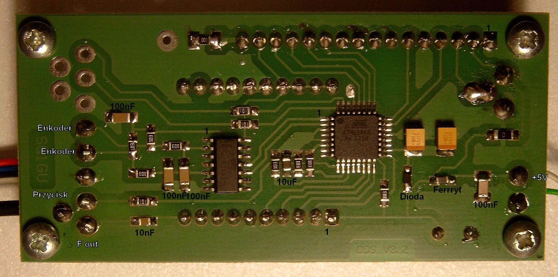
Parts list:
AD9850 boardl
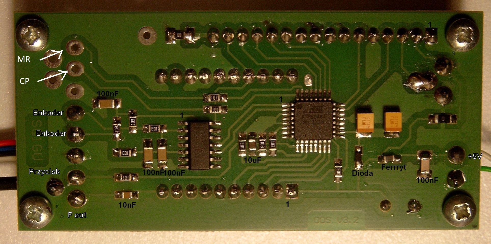
US1 – ATMEGA8a
US2 – CD4093
R10,R11,R12 – 100ohm
R1,R2,R3,R4,R5,R6,R7,R8,R9 – 10k
C1,C2,C3,C4 - 100nF
C5 - 10uF
C6 -10nF
C7,C8 - 100uF
C11- 1000uF
F – ferryte core
D1 - dioda shotky
P1- trimmer 10k
LCD 16x1 g
goldpin 16pin
dystans element
encoder EC11